KittenBot is a friendly programming platform to innovate with hardware and friendly to the educators, students and beginners.

Microcontrollers such as Micro:bit, S4A Arduino and commonly used sensors & outputs hardware.

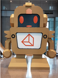
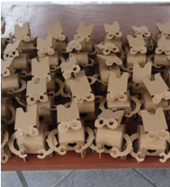
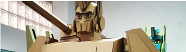
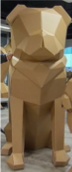
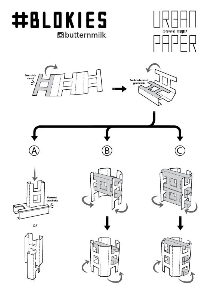
We make use of our #Blokies design as building materials. #Blokies pieces are cardboard designs where students are able to customize and build their own structures easily.


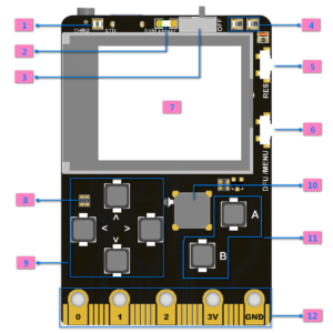
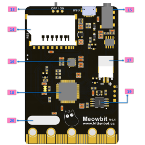
Meowbit is a card-sized graphical retro game computer with allows you coding with Makecode arcade and Python. In other words, it can use combines game programming with hardware devices.
Meowbit is a card-sized grahical programming video game console designed for teenagers. It contains 1.8′ full-color screen, 6 x programmable buttons ,1 x buzzer, built-in light sensor , temperatur sensor, SD card slot (For extenal stoage),multyplayer connector and edge connector. Espcially the edge connector could access most micro:bit expension boards. We recommend to use Robot:bit for Mewobit, it can help you create a robot quickly.
Makecode Arcade graphical programming mode
Arcade: https://arcade.makecode.com/
micropython programming mode
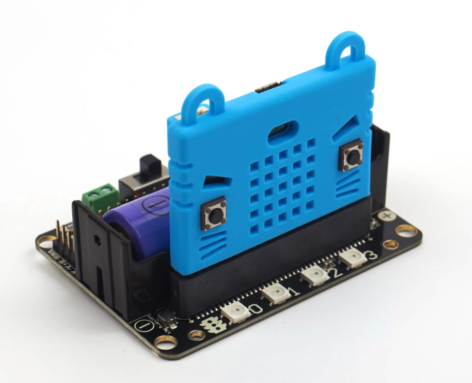
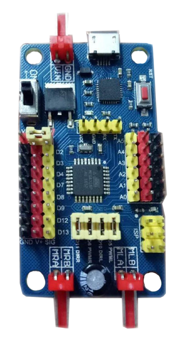
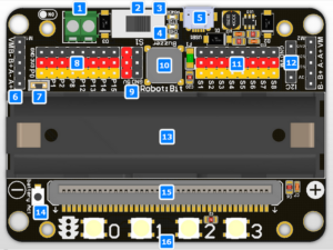
It has a powerful ability to drive DC motors, stepper motors, servos, and onboard buzzer and RGB pixels and release all valid IO from microbit, with support the most common electronics module in the market. It comes with 18650 battery holder, integrated lithium battery boost, charging and protection chip. Support for external power input. Mechnically support for KittenBot robotic chassis and LEGO technical slots. The powerful drive capability and built-in battery make DIY more convenient and free. We have received unanimous praise from the school teacher training institutions and individual enthusiasts. It is an excellent choice for your robotic projects based on Micro:bit!
Robotbit designed for primary school students/training institutions/parents/ enthusiasts as a robotic accessory.
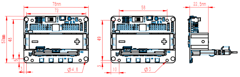
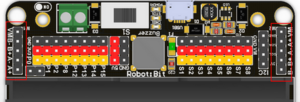
Robotbit is an excellent robotic expansion board specially designed for Microbit by KittenBot team. There is also a 3D printed protective case included.
Robotbit V2.1 X 1
Available Coding platform: Kittenblock(based on Scratch3.0) or Makecode and python(Mu editor in microbit mode)
MakeCode from Microsoft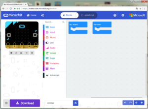
KittenBlock (Developed by Kittenbot Team based on Scratch 3.0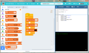
Python
If you’re used to code programming and want to get started by microbit python you have two options, directly Mu Editoror kittenblock in micropython editor mode.

In makecode add extension panel directly search Robotbit. In our offline version of makecode, you may find Robotbit in the default list and other useful extensions.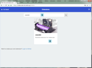

18650 Battery Case
Once you got your RobotBit extension board please first install a 18650 battery, pay attention to the positive and negative pole (even we have anti-reverse protection). You have to activate the power management system by pressing the Battery Act push button. Each time you switch a battery cell or let the power management go into protection mode (over current or over discharge), you have to redo this step.
18650 Power Switch
Turn on the switch (in the direction of green terminal input), will provide onboard 3.3V 5V and VM(motors and servos directly driver by battery cell)
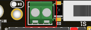
Micro USB charger port
![]()
Only for charging and not for download! Computer USB host port or any other mobile phone charger which may output 1A or larger should be fine and may take about 2.5 hours to fully charge a 18650 cell. it will automatically cut off once full, no need to worry about overshoot.
Power and battery indicator
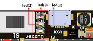
Led(3) is the power indicator, will be always on after switch is turned on. Led(1) is charging indicator, will be on while charing and Led(2) be on once fully charged.
Micro:bit stand edge connector
For installing Microbit mainboard. Please install Microbit with led matrix and RGB led in the same direction.
4x RGB neopixel
![]()
The robotbit extension for makecode has integrated neopixel support. Neopixel array connect to P16 of microbit.
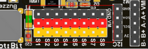
8 channel servo connector
Servos are driven by an extension chip (PCA9685) with the power source from battery or external input.The extension chip communicates with Microbit via the i2c interface, so these S1~S8 interfaces can only be used for pulse output not as common IO. With onboard 18650 battery cell, it may drive eight 9g hobby servo (with maximum current less than 2A). If you plan to use larger servos like MG995 please use an external power resource connect to the green slot (the input still 5V). Robotbit extension has built-in blocks for controlling servos.
4 channel DC motors / 2 channel 28BYJ micro steppers
Robotbit extension has also built-in blocks for DC motors and steppers. With onboard cell you may drive 4x TT motors or 2x 28BYJ steppers, or a mixture of theese. Keep in mind that VM may out 2A to motors and servos. If you use external source please keep the input around 5V or less, a high voltage external input may damage the 5V boost circuit.
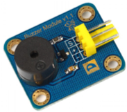
Buzzer and the selection jumper
The buzzer jumper cap is plugged in by default, and the corresponding buzzer is connected to the Micro:bit P0 port. If you need P0 for other purposes please unplug the jumper. The buzzer associate to music blocks in makecode.
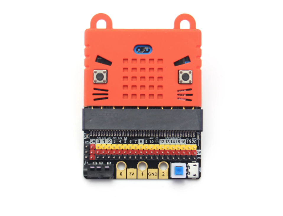
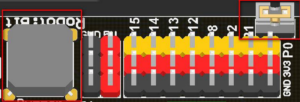
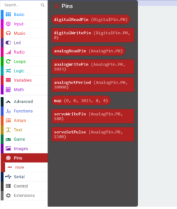
Micro:bit IO
We have released P0-P2、P8、P12-P15 from Microbit to Robotbit for common IO usage. P0~P2 has analog read/write support, others may act as digital IOs. You may connect commonly modules for Arduino to Robotbit, there is also 5V output in case your module only support 5V power input. Please note that Microbit IO signal level is 3.3V.
I2C Interface
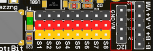
Expandable I2C module, can only be used to plug in I2C module.
2PIN External Power Input
Although there is anti-reverse protection, but still pay attention while wiring. The positive and negative silkink of this interface is on the back of Robotbit. You can only input 5V or less into this port. If you have a higher voltage source you may need a LDO or DC-DC module to buck the voltage down.
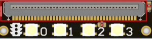
IObit, IO refers to (input, output), IObit as seen from the name is mainly to serve as pin outputs. It’s suitable for some DIY enthusiasts hoping to use all of the IO ports.
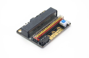
This is a low-cost expansion board for Micro:bit, which is specifically used for the IO ports of Micro:bit. It has taken all the IO resources on the Micro:bit, and also has a buzzer on the board. It is connected to the P0 pin through the jumper cap. The P0 pin can be released using a jumper cap. The small size is very suitable for small projects using Micro:bit.
IObit 2.0 X1
Length x width x height: 57mmx44mmx12mm
Technical Parameters
MakeCode/KittenBlock (based on Scratch3.0) with hardware: Micro:bit.
It is consistent with Micro:bit programming, because IObit does not have its own drive chip (except buzzer). The building block that is generally used with IObit is to operate the IO port. Many sensors on the market return a high and low voltage. Flat, or an analog value. For actuators, the microbit needs to output high and low level to control. People who are not familiar with this aspect can search Netease Cloud Classroom: Xiaoyan Technology and find the arduino tutorial, which explains how to use the commonly used sensors on the market, the principle is the same.
Before using the building blocks, you must first understand the control method or reading method of the electronic module you are using.
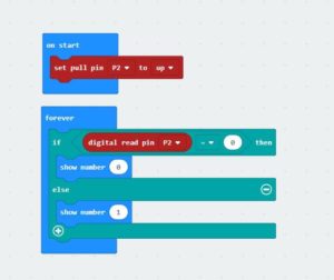
Most newbies will fall out of here because they often ignore setup pull-ups or pull-downs during initialization. So the level state will fail after reading it once. Therefore, we must pay attention to this. Micro:bit itself does not help to set up and down by default, you need to set it yourself.
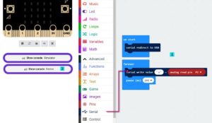
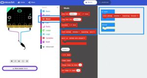
In response to the analog reading, because the analog reading will return a value of 0-1023, it is always inconvenient to display it with a dot matrix screen. So here we take advantage of the unique serial port debugging function of the MakeCode offline version produced by Xiaoyan. First, download the program shown in the figure to open the serial port. In step 2, the console of the device will appear, you can see the data returned in real time.
Digital read here does not need to set up and down
Simulated writing an example of a flashing light

The most commonly used IO port operation is one of these four types. After you master it, you should have no problem with the commonly used sensors on the market. Another thing to note is that the sensors on the market are 5v and 3.3V compatible. But some can only work in 5V. For example, the blue ultrasonic wave that Taobao sells can ordinarily only work in 5V. If IObit is connected, the number read back will always be 0, because the module is not working properly!

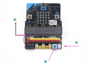
Insert the USB power supply (5V 1A) as shown in Figure 1. Press the blue button at 2, and the red indicator light at 3 will light up. You can use the left 5V interface.
Toggle switch to turn off the buzzer function (see the silk screen on the back of the board for status)
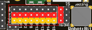
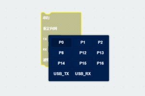
3Pin IO port leads
All the pins in the Micro:bit have been taken out without any reservation (Note: there are no P17 and P18 on the Micro:bit, it’s not that the IObit is not taken out)
Yellow corresponds to the different IO pins
Red corresponds to 3.3V/5V (with silkscreen)
Black corresponds to GND
5PIN gold fingers
The gold fingers of the Micro:bit are used to draw 3v, gnd, P1, P2, and P3 respectively. This is for users who prefer to use alligator clips
Compact size socket
The two outermost holes are approximately 4.8 mm in diameter and are compatible with Lego friction pins with a spacing of 48 mm.
You can plug in a 3.5mm jack audio device and play the sound of the P0 pin.
If you haven’t gotten started with Micro:bit, first get started with Micro:bit, this is the operating premise.
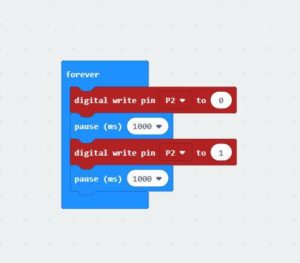
Use music blocks directly in MakeCode to
If you use P0, remember to turn the buzzer toggle switch off (because the buzzer is combined with P0)

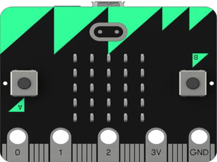
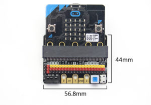
The micro:bit is a handheld, fully programmable computer with a lot of built-in features:
The S4A Arduino is a handheld, fully programmable computer with a lot of features:
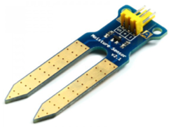
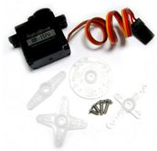
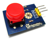
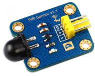
List of some of the commonly used sensors & outputs


We make use of our #Blokies design as building materials. #Blokies pieces are cardboard designs where students are able to customize and build their own structures easily.